What you'll need
|
Information to gather from your SIP server administrator ▢ SIP server domain name or IP address ▢ SIP server port (5060 UDP/TCP, 5061 TLS, or custom) ▢ Transport protocol (UDP, TCP, or TLS) ▢ Extension number assigned to Rock device ▢ Authentication username and password (configured from the SIP server) ▢ CA certificate - only if Transport is TLS Note: Required Admin Portal role - Account Administrator |
- Account Administrator
Configure SIP
Step 1 - Open the SIP Configuration panel
- Log in to the Alcatraz Admin Portal as an Account Administrator.
- In the left menu, go to Device Management → Devices.
- Click the Rock device you want to configure.
- From the Settings drop-down menu on the right, select Modify.
- Scroll to the bottom of the Device configuration list and expand SIP Configuration.
- Toggle SIP on.
Step 2 - Enable SIP
Toggle SIP on. The full configuration form appears.
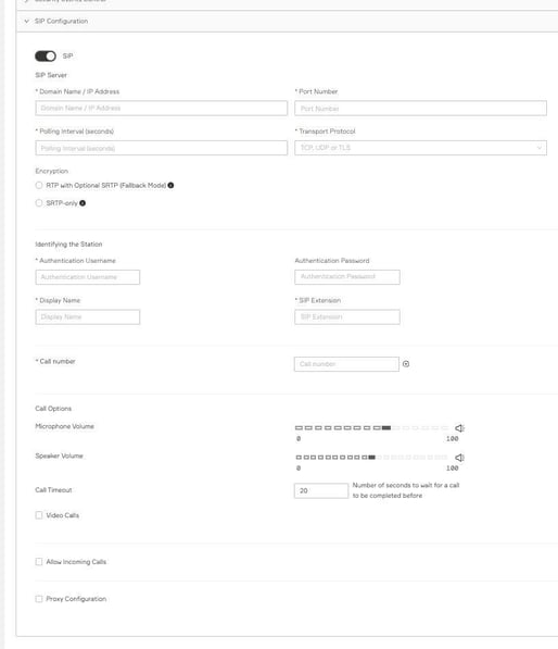
The SIP Configuration panel after enabling the SIP toggle.
Step 3 - SIP Server
Connection details for the SIP server through which the device places and receives SIP calls.
|
Field |
Example |
Description |
|
Domain Name / IP Address |
10.40.0.224 |
IP address or domain name of the SIP server. |
|
Port Number |
5060 |
Port the SIP server uses. Common defaults: 5060 (UDP/TCP), 5061 (TLS). |
|
Polling Interval (seconds) |
30 |
How often the device confirms connectivity with the SIP server. 30 seconds keeps overhead low; longer intervals mean it takes longer to notice if the SIP server goes offline. |
|
Transport Protocol |
TCP |
UDP, TCP, or TLS. |
TLS Certificates (TLS only)
Optionally upload a CA certificate to validate the server's TLS certificate. Supported format: .pem
|
When to upload a CA certificate • The SIP server uses a self-signed or private CA certificate. • The server's certificate is signed by an intermediate or root CA that is not in the device's default trust store. |
Encryption
Encryption controls whether the media stream (audio and video) is secured with SRTP. It is independent of the Transport Protocol setting, which secures SIP signaling.
|
Option |
Behavior |
|
RTP with Optional SRTP (Fallback Mode) |
The device prefers SRTP. If the remote endpoint does not support SRTP, the device falls back to unencrypted RTP. |
|
SRTP-only |
The device requires SRTP. Calls fail if the remote endpoint cannot establish SRTP. |
|
Recommendation Use SRTP-only when the SIP server requires encrypted media. Use RTP with Optional SRTP when interoperating with mixed environments where some endpoints may not support SRTP. |
Step 4 - Identifying the Station
These settings tell the SIP server who this device is.
|
Field |
Example |
Description |
|
Authentication Username |
505 |
The username assigned to this device on the SIP server. Usually matches the SIP Extension. Letters and numbers only. |
|
Authentication Password |
**** |
The password assigned to this device on the SIP server. |
|
Display Name |
RockX-505 |
A name shown on the receiving endpoint. A common convention is to include the extension, |
|
SIP Extension |
505 |
The extension number assigned to this device on the SIP server. |
Step 5 - Call number
|
Setting |
Example |
Description |
|
Call number |
400 |
The extension is dialed when someone presses the intercom button. Enter the extension only |
Step 6 - Audio & Video control / "Call Options"
|
Setting |
Description |
|
Microphone Volume |
Input level of the device's built-in microphone (0-100). |
|
Speaker Volume |
Output level of the device's built-in speaker (0-100). For outdoor or noisy installations, test before finalizing - high speaker volume in compact installations can cause acoustic feedback. |
|
Call Timeout |
Number of seconds to wait before ending the call if no one answers. Recommended: 30-40 |
|
Video Calls |
Enables video on calls. Options: Outgoing only, Incoming only, or Both. |
Step 7 - Allow Incoming Calls
Check Allow Incoming Calls to let other endpoints reach this device. A list of permitted SIP URLs appears below. Click the plus icon to add more entries. Use the full SIP URL format:
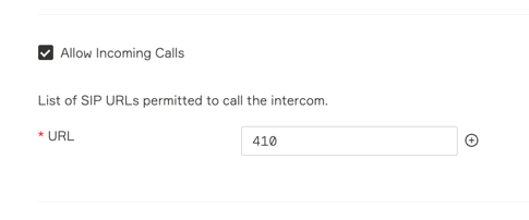
v3.6.3 - Allow Incoming Calls expanded. Add each permitted caller's SIP URL.
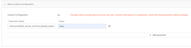
Advanced - let the SIP server control allowed callers
By default, v3.6.3 enforces the allowed-callers list locally on the device. If you want the SIP server to handle authorization instead, add a custom configuration parameter:
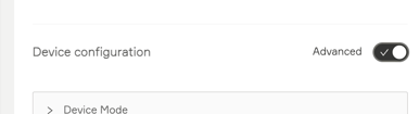
- In the device's Modify page Open Advanced configuration option
- Then scroll to the Custom Configuration section.
- Click Add a Custom Configuration.
- Enter the parameter name intercom.default_server_controls_allowed_callers.
- Set the value to true.
- Click Submit. The device reloads its settings automatically.
|
When to use this • Use the default (extension list) when you want device-level enforcement, or when the SIP server does not authenticate inbound endpoints. • Use the custom configuration when your SIP server (Sipelia etc) already enforces dial plans, ring groups and you don't want to maintain a duplicate allowlist on each device. • Important: the device cannot identify ring group membership on its own - ring group allow/deny must be enforced on the SIP server side. |
|
Coming in v3.6.4 - built-in UI option v3.6.4 promotes the server-controlled behavior to a built-in UI radio under Allow Incoming Calls, so the custom configuration parameter is no longer required: • Managed by SIP Server - NEW / more user friendly • Restricted by Extension List - same behavior as the v3.6.3 default (local URL list). |
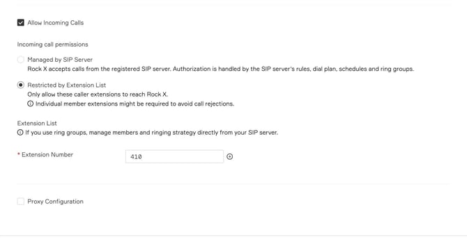
Preview - v3.6.4 Allow Incoming Calls UI with the new mode selector.
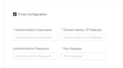
Step 8 - Proxy Configuration (optional)
Configure “Proxy Configuration” only if your network requires SIP traffic to traverse a proxy server before reaching the SIP server.
|
Field |
Description |
|
Authentication Username |
Username to authenticate against the proxy server. |
|
Authentication Password |
Password to authenticate against the proxy server. |
|
Domain Name / IP Address |
IP address or domain name of the proxy server. |
|
Port Number |
Port the proxy server uses for incoming connections. |
Step 9 - Submit
Click Submit at the bottom of the Modify Device Parameters page. The device applies the new configuration without requiring a reboot. Once registered, Rock is ready to place and receive calls.
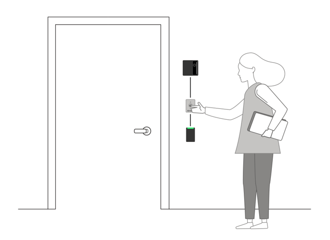
Diagram: SIP-based intercom architecture using RockX as the intercom endpoint.
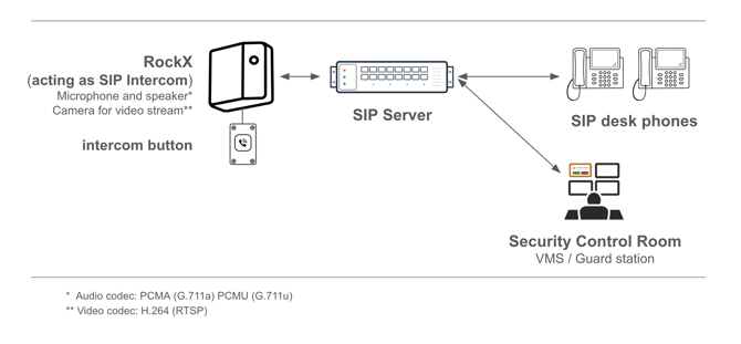
RockX operates as a SIP-based smart intercom device that initiates calls through a SIP server to desk phones and security control room operators, enabling centralized audio and optional video communication for entry management and visitor assistance.
Example: Genetec Sipelia
Use these values as a template when integrating a Rock device with Genetec Sipelia. Replace the placeholder values with the ones your Sipelia administrator provides. This example shows the Rock side only - the Sipelia side is configured per Genetec's documentation.
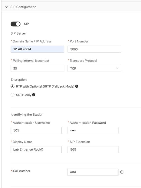
Top of the SIP Configuration form, populated with the example values.
Verify it works
Run these two tests after submitting the configuration. They confirm both call directions and that the device is logging events correctly.
Test 1 - Outgoing call (RockX - intercom button → SIP server)
- On the device side, press the intercom button (wired).
- Confirm the device's screen shows the dialing state.
- Confirm the receiving station / SIP phone rings.
- Answer on the receiving side and confirm two-way audio (and video - if configured)
- Press the intercom button again to end the call.
- In the Admin Portal, open Security Events and filter for Dialing - to Confirm an event was logged at the time of the test.


RockX screen - dialing state shown when the intercom button is pressed.
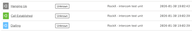
AHP: Scenario A: call established - signaling success. Hanging Up indicates a call ended normally by one side.
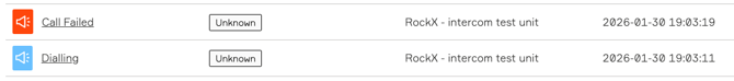
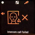
AHP: Scenario B: when the remote endpoint rejects or declines the call
Alcatraz Platform - Intercom security events
The intercom function generates these events. Use them to verify a successful call, or to diagnose a failed one. To access events, go to Security Events in the Admin Portal.
|
Event Name |
Description |
|
Dialing |
An outgoing call attempt has started - generated when the intercom button is pressed. |
|
Call Established |
The remote station answered. Audio channels are open. |
|
Call Failed |
A single outgoing call failed. Event details indicate the failure reason. |
|
Hanging Up |
An outgoing call ended; the remote side hung up. |
|
Call Failed |
All configured fallback numbers were tried; none answered. |
|
Call Rejected |
The device rejected an incoming call. Most common reason: caller not in the Allow Incoming Calls list. |
|
Incoming Call |
An incoming call was established. |
|
Call Failed |
An incoming call failed after being established. |
|
Hanging Up |
An incoming call ended; the remote side hung up. |
|
Hanging Up |
An incoming call ended; the device side hung up. |
Call button setup
The RockX supports two types of call buttons. Use the option that fits your installation.
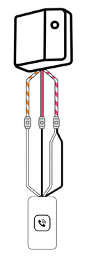
Wired call button
You will need a Rock X device with the panel cable, and an external push button (black cable with black/white conductors). If calls do not start when the physical button is pressed, verify wiring and confirm that the Rock X detects the button press.
Wiring connections
RockX [PINK] wire → BLACK (1) wire from the push button
RockX [WHITE-ORANGE] → WHITE (1) wire from the push button.
RockX [WHITE-PINK] → BLACK (2) and WHITE (2) wire from the push button.
For best results, speak close to the device (less than 3 ft OR 1 m away).